E-R Diagram – Student Management system
E-R (Entity-Relationship) Diagram is used to represents the relationship between entities in a table. ER diagrams represent the logical structure of databases. ER Diagram represent relationship between two database tables.
E-R diagram means Entity Relationship diagram. Entity is a object of system, generally we refer entity as database table , the e-r diagram represent the relationship between each table of database. E-R diagram represent entity with attributes, attributes is a properties of entity. If we assume entity is a database table then all the columns of table are treat as attributes.
ER Diagram
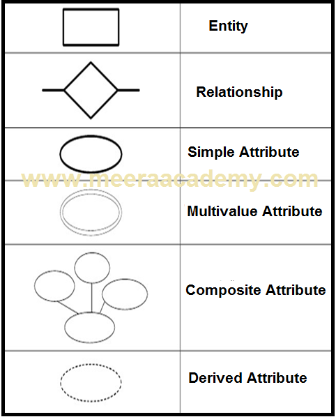
Entity : Entities are represented by rectangle. All table of database are treat as entity.
Attributes : Attributes are represented by ellipses. Attributes are properties of entities.
ER Diagram Symbols
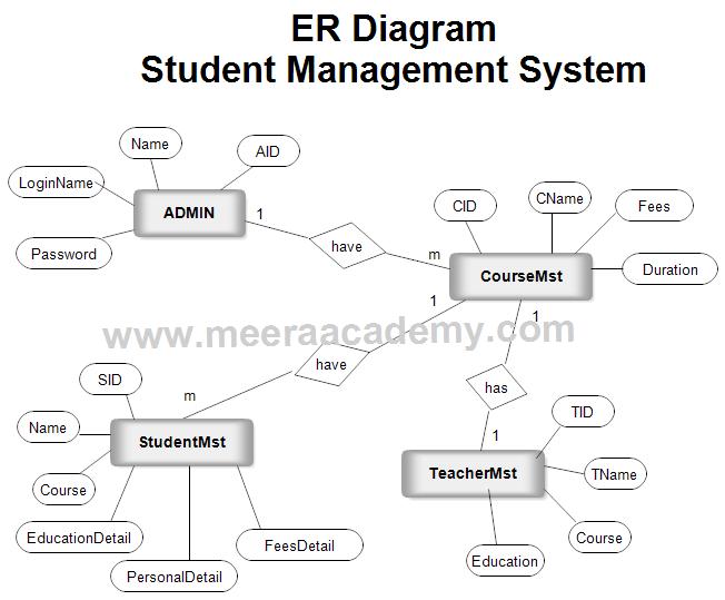
ER Diagram – Student Management System
Download Student Management System Project.

Ok
Ok but we want project
Download link is already given in above post.